Your cart
There are no more items in your cart


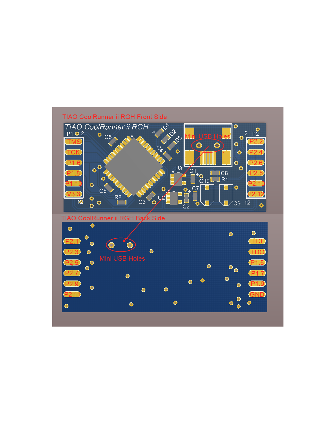
TIAO Xilinx CoolRunner-II Dev Board Overview
When we designed this board, we only had on goal in our mind: make it simple. Simple to install, simple to use. We achieved it. You don't need to solder any components, no jumper wires, it even provides a on-board 5v to 3.3v LDO (Low-drop Voltage Regulator) for JTAG programming. One board works for all.
Key features:
- Pre-populated required components for phat: 100nF Cap, 1K and 22K Resistors, three 1N4148 Diodes.
- Pre-populated required component for slim: 220pF cap. However, we also added two 3-30pF trimmer capacitors, thus the capacitance can be easily adjusted from 226pF to 280pF.
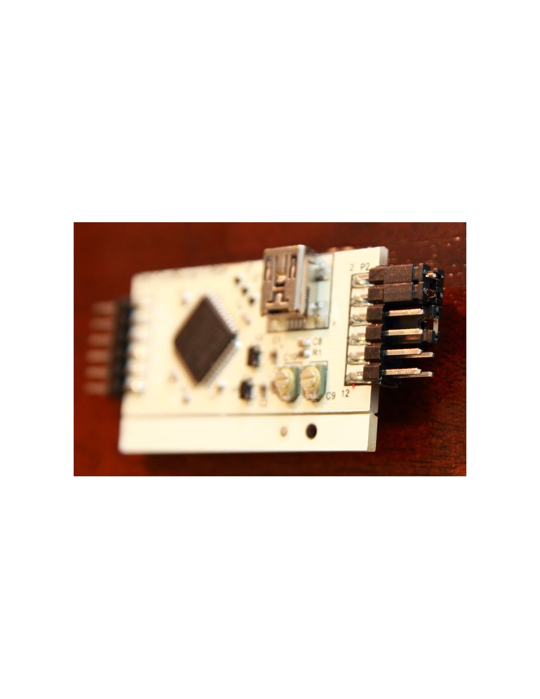
- The dev board ships with four female to female (50cm / 20 inch in length) flexible wires, cut the wires in half, solder one end to your mother board and insert the female headers to the pins on our dev board. This allows you to quickly remove the board for upgrading or testing.
It is fairly easy to program TIAO CoolRunner-II Dev Board. All you need to do is to connect the JTAG pins (TDI, TDO, TMS and TDO) to the corresponding pins on your JTAG programmer.
If you have parallel port, we suggest to use our Universal JTAG Adapter to program the CPLD. As you can use the same adapter to read/write the 360 NAND.
- Config TIAO Universal JTAG Cable As A Buffered Xilinx Parallel Platform Cable III
- Program Xilinx XC2C64A Or Similar Xilinx CPLD Using TIAO Universal JTAG Cable
However, if you don't have parallel port on your pc, we have USB Programmer for you:
- How to program Xilinx CPLDs using TIAO USB Multi-Protocol Adapter (TUMPA) on Windows or Linux - program the XC2C64A
- Read/write 360 NAND via USB
As to power the CPLD, you can either use external +3.3V power source (available on our Universal JTAG adapter) to power your our CoolRunner-II, (the board has built in 1.8v LDO), or power it by USB (use the on board USB connector. The board has built in 3.3v and 1.8v LDO). However when choosing different power source, you need to move jumpers on different headers.
When powering it by onboard USB connector, you need to put a jumper on P2.11 and P2.13 (see pic below). After you have programmed it, move the jumper to the original position.
No reviews
Tap to zoom