Your cart
There are no more items in your cart

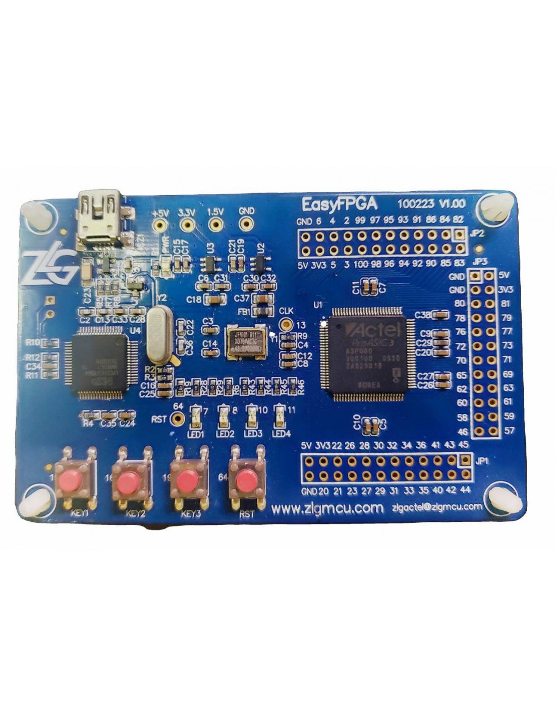
With 4 buttons and 4 LEDs, simple input and output control can be achieved;
ico_circle_1.gif All I/O ports are brought out to facilitate users to expand the peripherals they need;
An ARM-LPC2141 is added to the ico_circle_1.gif board to implement the USB download interface, which allows users to download via the USB interface without having to purchase a downloader separately;
The FlashROM inside ico_circle_1.gif can realize version control, serial number, password setting, and other information storage;
Instructions for use:
1. Basic sending and receiving
1: Both the receiving and sending code formats can be set to HEX or CHR.
2: The scheduled sending function can be accurate to milliseconds, but it cannot be too fast (sending is exclusive, and the function will not return until all data are sent). If the next frame of data is sent before the previous frame of data is sent, an error will occur.
3: Please use ft232 serial port chip or chip that supports high baud rate, otherwise the baud rate cannot be set too high.
2. Advanced code collection
1: The received code is displayed in HEX format.
2: The lower computer sends custom data in the format of 0x88+FUN+LEN+DATA+SUM. FUN can be 0xA1 to 0xAA, a total of 10; LEN is the length of DATA (excluding 0x88, FUN, LEN, SUM). SUM is the sum of 0x88 to the last byte of DATA, in uint8 format. (Remember to turn on the switch that needs to use the frame, and click Save Settings after changing the settings to make the settings effective)
3: The data can be in the common formats of uint8, int16, uint16, int32, and float. Multi-byte data has the high bit first.
4: There are 20 data memories in total, each of which can be set to 30 data from 10 custom frames respectively.
5: When communicating at high speed (2ms per frame or faster), please turn off the data display button on the advanced code receiving page, otherwise the program may freeze due to too fast update.
6: The frame FUN corresponding to the flight control display is 0xAF. (Frame format: 0x88+0xAF+0x1C+ACC DATA+GYRO DATA+MAG DATA+ANGLE DATA+VOLTAGE + 0x00 0x00+SUM, 32 bytes in total. ACC/GYRO/MAG/ANGLE (roll/pitch/yaw)/VOLTAGE data are int16 format, where ANGLE's roll and pitch data and VOLTAGE are integer values obtained by multiplying the actual value by 100, and yaw is an integer value obtained by multiplying by 10. The host computer divides them by 100 and 10 when displaying.)
7: The frame FUN corresponding to the remote control display is 0xAE, (frame format: 0x88+0xAE+0x12+THROT YAW ROLL PITCH AUX1 2 3 4 5+SUM, a total of 16 bytes), the data is in uint16 format, the minimum remote control data is about 1000, and the maximum is about 2000. Tips: If the purpose of high-speed communication is to draw waveforms, only open the waveform display and only keep the waveforms that need to be observed. If it is to observe data, turn off the waveform display and only keep the received code display, which can speed up the program response speed.
7: The fastest communication speed has been tested. The lower computer uses a 500K baud rate and sends 32 bytes of data every 1ms. The upper computer displays 6 waveforms, OK! (It may be related to the computer configuration)
3. Waveform Display
1: There are 20 waveforms in total, corresponding to 20 data memories.
2: Double-click the waveform drawing area to turn on the waveform display switch.
3: Hold down Ctrl and click a waveform with the left mouse button to display the data label. Click again to hide it.
4: Press and hold the left mouse button, drag from one point to the lower right in the drawing area, and then release it to zoom in on the framed waveform area. You can zoom in multiple times.
5: Press and hold the left mouse button, drag from one point to the upper left in the drawing area, and then release it to restore the enlarged waveform.
6: Press and hold the right mouse button and drag up, down, left, and right in the drawing area to move the waveform.
7: Press F9 when the waveform is displayed to open the advanced waveform settings.
4. DEBUG function
1: During the debugging process, certain flags, registers, and variables can be sent back to the host computer in real time and displayed on the DEBUG page.
2: The communication format is: 0x88 + 0xAD + len + num + DATA + SUM, len is the total length of num and DATA, num indicates which display state to change, for example, num = 0x01 means to change the first LED, num = 0x07 means to change the first digital output display. When changing the LED, DATA only needs one byte, DATA = 0x00 means turning off the LED, and greater than 0x00 means turning on the LED; when changing the digital output, DATA needs two bytes.
Section, represents a uint16 number, with the high byte first. SUM is the sum check from 0x88 to the byte before SUM, in uint8 format. For example: sending 0x88 + 0xAD + 0x02 + 0x01 + 0x01 + 0x39 means lighting up the first LED. Sending 0x88 + 0xAD + 0x03 + 0x07 + 0x00 + 0x05 + 0x44 means displaying 5 at the first digital output position.
5. Keyboard and mouse control
1: The control data sending format is: 0x88 + 0xA1 + 0X1C + THROT YAW ROLL PITCH AUX1 AUX2 AUX3 AUX4 AUX5 + 0x00 0x00 0x00 0x00 0x00 0x00 0x00 0x00 0x00 + SUM. The remote control data are all in int16 format, with a median value of 1500, and minimum and maximum values of 1000 and 2000.
2: Transmitting frequency 50Hz.
3: Mouse up and down controls throttle, left and right controls YAW, keyboard WASD controls ROLL/PITCH, keyboard 12345 controls AUX12345. A total of 9 channels.
No reviews
Tap to zoom